| HOME |
|
Infos |
|
|
|
DMX |
|
|
|
Miscellaneous |
|
|

DMX Analyzer
 |
This firmware was designed more for "DMX freaks" than for ordinary users. With the help of the analyzer, the signal of DMX consoles or PC interfaces can be evaluated and checked for compliance with the current standards.
|
In addition, the analyzer can transmit a DMX signal in order to test receivers such as dimmer packs or moving lights.
In addition, the start address and the operating mode (personality) of RDM-capable devices can be set.
The analyzer consists of a DMX Transceiver and a 4x20 char Text-LCD (HD44780 compatible). An encoder with push button is used as user interface: A short press confirms an entry. A long press returns to the previous menu.
The behaviour is additionally controlled via the DIP switches: DIP1 activates the RDM function. If DIP2 is on, the Identify command is sent to the currently selected RDM device. If DIP3 is on, the device label is displayed instead of the RDM UID, if possible.
DMX Transceiver (Rev. 3.2)
With this module, DMX data can be sent and received. However, due to using a microcontroller, this circuit is not ideal for beginners.
The Transceiver is suitable for bidirectional communication (e.g. RDM according to ANSI E1.20) due to the complete connection of the RS485 converter.
Industrial-quality circuit boards are available in the shop.
 part list
| IC1 IC2 IC3 D1 LED1 LED2 R1 R2,3,4 C1,2 C3,4 C5,6 SW1 Q1 connectors |
ATmega8515-16PU (+socket!) 75176B (+socket!) 7805 1N4007 LED 5mm red LED 5mm green 10k (PT10-S) 390 Ohm 27pF 100nF 100µF DIP switch (10x) 8MHz (HC49) pin header RM2.54 |
As you can see, the circuit is quite simple: All the magic happens in firmware within the MCU (IC1). It is transferred to IC1 via the "ISP"port. The start address and special options (if any) are set via ADR. The LEDs serve as status indicators. The voltage regulator IC3 ensures a stable operating voltage of 5V. Q1 and C1,2 are needed for an operating frequency of 8MHz. The RS485 converter IC2 allows the MCU to communicate with the DMX universe. With the help of "Spare", various firmware options can be jumpered. Via A-Input, an analogue threshold value (e.g. for thermal protection) can be read.
A supply voltage between 9V and 12V dc is connected to PWR. The DMX Transceiver itself requires <300mA. When selecting the power supply, all loads must be taken into account.
pcb layout (48 * 76 mm^2; 300dpi)
|
placement
|
The transceiver is connected to the DMX bus as shown in the next diagram:
Attention: Pin 3 of the XLR connectors is connected to the middle pin of the PCB connector!
Instructions for programming and selection of clock sources can be found under 'Resources'.
After changing the clock source, the Analyzer firmware can be transferred to the DMX Transceiver.
LC-Display (HD44780 compatible)
The LCD is connected to the output of the Transceiver using the following table. The pin assignment of the LCD can be found in its data sheet.
| LCD | Transceiver | Signal |
| D4 | Out1 (PA0) | data |
| D5 | Out2 (PA1) | data |
| D6 | Out3 (PA2) | data |
| D7 | Out4 (PA3) | data |
| RS | Out5 (PA4) | register select |
| E | Out6 (PA5) | enable |
| Vo | 0-0.5V (10k Pot) | contrast |
| R/W | GND | read / write |
| GND | GND | ground |
| VCC | VCC | +5V |
Push buttons
The analyzer is controlled by a rotary encoder with a push-button that switches the SPARE inputs to GND:
| Transceiver | Function |
| SPARE1 (PD4) | A (Clk) |
| SPARE2 (PD5) | B (DT) |
| SPARE3 (PD6) | Button |
How it works
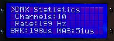 |
DMX Statistics In this mode, the size of the universe and the refresh rate are determined. Additionally the timing of the incoming DMX frames is measured. A new frame is indicated by a Break, in order to synchronise all receivers. This is followed by a Mark After Break to clearly distinguish the break from the subsequent start byte. A DMX start byte has always a value of 0. After the start byte the individual channels are transmitted. According to the standard E1.20 the following timing is permissible: Size: max. 512 channels
|
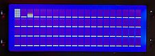 |
DMX Overview 80 consecutive DMX channels are displayed as a bargraph. The encoder can be used to select the section being viewed.
|
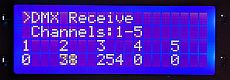 |
DMX Input The values of five consecutive DMX channels are displayed as decimal numbers. The channels can be selected with the encoder.
|
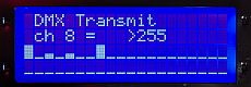 |
DMX Output In this mode, 40 DMX channels are transmitted. The rotary encoder is used to set the value for each individual channel. With a refresh rate of 100Hz and inter byte gaps of 5us, most DMX receivers should be able to cope without any problems.
|
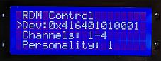 |
RDM Controller With remote device management the start address and the personality of connected RDM devices can be changed remotely. For this purpose, the UIDs of all RDM devices are first determined via a full discovery. After selecting a device, an Identify command is sent to this device - if desired - and the device information is requested. If enabled, the device label can be displayed instead of the UID. Next, the start address and finally the personality can be changed.
|