| HOME |
|
Infos |
|
|
|
DMX |
|
|
|
Miscellaneous |
|
|

2 channel DMX stepper motor control
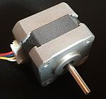
With this circuit, two unipolar or bipolar stepper motors with a full-step angle of 1.8°, 7.5° or 18° can be controlled independently of each other with a resolution of 16bit.
If using microstep drivers, four additional PWM channels are optionally available for dimming LEDs.
A stepper motor controller consists of a DMX Transceiver, and either one ULN2803 driver - for unipolar steppers - or two L298 - for bipolar steppers - or two microstepping drivers like A4988 connected to its output. The stepper motors absolutely need a powerful power supply to prevent voltage drops at the Transceiver!
DMX Transceiver (Rev. 3.2)
With this module, DMX data can be sent and received. However, due to using a microcontroller, this circuit is not ideal for beginners.
The Transceiver is suitable for bidirectional communication (e.g. RDM according to ANSI E1.20) due to the complete connection of the RS485 converter.
Industrial-quality circuit boards are available in the shop.
 part list
| IC1 IC2 IC3 D1 LED1 LED2 R1 R2,3,4 C1,2 C3,4 C5,6 SW1 Q1 connectors |
ATmega8515-16PU (+socket!) 75176B (+socket!) 7805 1N4007 LED 5mm red LED 5mm green 10k (PT10-S) 390 Ohm 27pF 100nF 100µF DIP switch (10x) 8MHz (HC49) pin header RM2.54 |
As you can see, the circuit is quite simple: All the magic happens in firmware within the MCU (IC1). It is transferred to IC1 via the "ISP"port. The start address and special options (if any) are set via ADR. The LEDs serve as status indicators. The voltage regulator IC3 ensures a stable operating voltage of 5V. Q1 and C1,2 are needed for an operating frequency of 8MHz. The RS485 converter IC2 allows the MCU to communicate with the DMX universe. With the help of "Spare", various firmware options can be jumpered. Via A-Input, an analogue threshold value (e.g. for thermal protection) can be read.
A supply voltage between 9V and 12V dc is connected to PWR. The DMX Transceiver itself requires <300mA. When selecting the power supply, all loads must be taken into account.
pcb layout (48 * 76 mm^2; 300dpi)
|
placement
|
The transceiver is connected to the DMX bus as shown in the next diagram:
Attention: Pin 3 of the XLR connectors is connected to the middle pin of the PCB connector!
Instructions for programming and selection of clock sources can be found under 'Resources'.
After adjusting the fuse bits, the stepper firmware can be transferred to the DMX Transceiver. After a reference run to the home position, this firmware evaluates the next four channels after the start address and generates the associated step sequences.
The configuration of driver type, homing, accelerations and maximum angles - i.e. the travel range - is done either with the software for Windows in the archive, which generates a file for the EEPROM of the AVR. This file should then also be transferred to the transceiver. Alternatively, the configuration via DMX is possible with Spare3 jumpered:
| Basic Settings [ch6 = 0 - 80] |
| DMX | Function | Value |
| ch1 | Driver | 0 - 60 : L298
70 - 120 : ULN2803 130 - 190 : A4988 200 - 255 : A4988 +PWM |
| ch2 | Homing | 0 - 60 : simultanneous 70 - 120 : X-Achse 1st 130 - 255 : Y-Achse 1st |
| ch3 | Auflösung | 0 - 120 : 8bit 130 - 255 : 16bit |
| Travel range [ch6 = 90 - 160] |
| DMX | Function | Value |
| ch1 | X-Position H | 0 - 255 |
| ch2 | X-Position L | 0 - 255 |
| ch3 | Y-Position H | 0 - 255 |
| ch4 | Y-Position L | 0 - 255 |
| Acceleration [ch6 = 170 - 255] |
| DMX | Funktion | Wert |
| ch1 | X-Acceleration | 0 - 255 |
| ch2 | Y-Acceleration | 0 - 255 |
| ch3 | X-Position | 0 - 255 (Test) |
| ch4 | Y-Position | 0 - 255 (Test) |
A short setting of ch5 to 255 (flashing) saves the respective parameter into the EEPROM.
Unipolar stepper motors are connected according to the following illustration:
Using bipolar stepper motors, a little more effort is required:
Alternatively, L293 D can be used in which the protection diodes are already integrated. Both circuits show only the connection of the first stepper - the second is connected in the same way via IN5..8.
Microstep drivers are to be wired according to its data sheet:
The transceiver provides the following signals: X-STEP= PA0; X-DIR= PA1; Y-STEP= PA2; Y-DIR= PA3.
If the operating mode "A4988 + PWM" is selected, PWM signals for controlling LEDs are available at PA4 - PA7.
The /Enable input of the driver is connected separately to GND.
The microstep resolution is configured via the MS inputs.
If you require accurate positioning and repeatability you may not want to rely on mechanical end stops for homing. In that case you can connect limit switches or light barriers to Spare1 and Spare2. A LOW signal is interpreted as home position.
Debugging
The ErrorLED should light up during start-up. A change in the relevant relevant DMX channels is acknowledged with a flashing of the green LED. An error is indicated by the ErrorLED flashing:
| Pattern | Error | Solution | |
|
|
single flashing | There is no signal present at the Transceiver. | Connect the Transceiver to the DMX bus. |
|
|
double flashing | The signal is not recognised as DMX. Not all required channels are received. |
Swap D+ and D- on the DMX connection. Transmit more channels or select a lower start address. |