| HOME |
|
Infos |
|
|
|
DMX |
|
|
|
Miscellaneous |
|
|

DMX servo controller with LED control
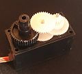
With this circuit, up to four standard servos can be controlled independently of each other with a resolution of 8bit.
Due to strong demand, an LED dimmer with up to four channels and strobe function was also integrated.
Common servo types can be easily selected via jumpers.
A servo controller consists of a DMX Transceiver to which the signal lines of the servos are connected directly. The servos need their own power supply!
DMX Transceiver (Rev. 3.2)
With this module, DMX data can be sent and received. However, due to using a microcontroller, this circuit is not ideal for beginners.
The Transceiver is suitable for bidirectional communication (e.g. RDM according to ANSI E1.20) due to the complete connection of the RS485 converter.
Industrial-quality circuit boards are available in the shop.
 part list
| IC1 IC2 IC3 D1 LED1 LED2 R1 R2,3,4 C1,2 C3,4 C5,6 SW1 Q1 connectors |
ATmega8515-16PU (+socket!) 75176B (+socket!) 7805 1N4007 LED 5mm red LED 5mm green 10k (PT10-S) 390 Ohm 27pF 100nF 100µF DIP switch (10x) 8MHz (HC49) pin header RM2.54 |
As you can see, the circuit is quite simple: All the magic happens in firmware within the MCU (IC1). It is transferred to IC1 via the "ISP"port. The start address and special options (if any) are set via ADR. The LEDs serve as status indicators. The voltage regulator IC3 ensures a stable operating voltage of 5V. Q1 and C1,2 are needed for an operating frequency of 8MHz. The RS485 converter IC2 allows the MCU to communicate with the DMX universe. With the help of "Spare", various firmware options can be jumpered. Via A-Input, an analogue threshold value (e.g. for thermal protection) can be read.
A supply voltage between 9V and 12V dc is connected to PWR. The DMX Transceiver itself requires <300mA. When selecting the power supply, all loads must be taken into account.
pcb layout (48 * 76 mm^2; 300dpi)
|
placement
|
The transceiver is connected to the DMX bus as shown in the next diagram:
Attention: Pin 3 of the XLR connectors is connected to the middle pin of the PCB connector!
Instructions for programming and selection of clock sources can be found under 'Resources'.
After adjusting the fuse bits, the servo firmware can be transferred to the DMX Transceiver. This firmware evaluates the next seven channels after the start address and generates the various PWM signals.
DMX footprint to control four servo motors
| DMX | Function | Output pin |
| ch1 | Position Servo1 | OUT1 (PA0) |
| ch2 | Position Servo2 | OUT2 (PA1) |
| ch3 | Position Servo3 | OUT3 (PA2) |
| ch4 | Position Servo4 | OUT4 (PA3) |
DMX footprint in moving light mode
| DMX | Function | Output pin |
| ch1 | Servo1 (Tilt) | OUT1 (PA0) |
| ch2 | Servo2 (Pan) | OUT2 (PA1) |
| ch3 | Strobe | |
| ch4 | PWM1 (red) | OUT5 (PA4) |
| ch5 | PWM2(green) | OUT6 (PA5) |
| ch6 | PWM3 (blue) | OUT7 (PA6) |
| ch7 | PWM4 | OUT8 (PA7) |
If the LEDs react inverted in your application (0=full on; 255=off), the PWM output can be inverted by setting the Spare1 jumper.
Calibration of the servo signals
A standard rc servo expects a PWM signal with a frequency of 50Hz and a duty cycle of 1ms to 2ms. However, many manufacturers do not adhere to this standard and allow greater travel distances by higher duty cycles. For this reason, the ranges of the servos can be calibrated as follows:
- Set DMX channels 1 to 5 to 50%.
- Set a jumper on Spare2. Attention: The servos now operate in a very large travel range and are limited by the mechanical end stops!
- Carefully reduce DMX channels 1 to 4 until the minimum positions of the four servos are reached.
- Set DMX channel 5 to 0%. The minimum positions are stored in the EEPROM.
- Set DMX channel 5 back to 50%.
- Increase DMX channels 1 to 4 carefully until the maximum positions of the four servos are reached.
- Set DMX channel 5 to 100%. The maximum positions are stored in the EEPROM.
- Set DMX channel 5 back to 50% and finally remove the jumper on Spare2.
Debugging
The ErrorLED should light up during start-up. A change in the relevant relevant DMX channels is acknowledged with a flashing of the green LED. An error is indicated by the ErrorLED flashing:
| Pattern | Error | Solution | |
|
|
single flashing | There is no signal present at the Transceiver. | Connect the Transceiver to the DMX bus. |
|
|
double flashing | The signal is not recognised as DMX. Not all required channels are received. |
Swap D+ and D- on the DMX connection. Transmit more channels or select a lower start address. |