| HOME |
|
Infos |
|
|
|
DMX |
|
|
|
Miscellaneous |
|
|

DMX switch pack
The DMX switch pack controls up to 8 channels. It can be operated both single-phase and multi-phase. A maximum load of 2kW per channel may be connected. A thermal protection prevents damage caused by insufficient cooling.
If a transistor array (e.g. ULN2803A) is connected instead of the power modules, conventional relays, DC motors or even solenoid valves can also be controlled.
A DMX switch pack consists of the following modules:
1 DMX Transceiver
1-8 power modules
The switch pack can run either on a conventional DMX firmware or an RDM firmware.
DMX Transceiver (Rev. 3.2)
With this module, DMX data can be sent and received. However, due to using a microcontroller, this circuit is not ideal for beginners.
The Transceiver is suitable for bidirectional communication (e.g. RDM according to ANSI E1.20) due to the complete connection of the RS485 converter.
Industrial-quality circuit boards are available in the shop.
 part list
| IC1 IC2 IC3 D1 LED1 LED2 R1 R2,3,4 C1,2 C3,4 C5,6 SW1 Q1 connectors |
ATmega8515-16PU (+socket!) 75176B (+socket!) 7805 1N4007 LED 5mm red LED 5mm green 10k (PT10-S) 390 Ohm 27pF 100nF 100µF DIP switch (10x) 8MHz (HC49) pin header RM2.54 |
As you can see, the circuit is quite simple: All the magic happens in firmware within the MCU (IC1). It is transferred to IC1 via the "ISP"port. The start address and special options (if any) are set via ADR. The LEDs serve as status indicators. The voltage regulator IC3 ensures a stable operating voltage of 5V. Q1 and C1,2 are needed for an operating frequency of 8MHz. The RS485 converter IC2 allows the MCU to communicate with the DMX universe. With the help of "Spare", various firmware options can be jumpered. Via A-Input, an analogue threshold value (e.g. for thermal protection) can be read.
A supply voltage between 9V and 12V dc is connected to PWR. The DMX Transceiver itself requires <300mA. When selecting the power supply, all loads must be taken into account.
pcb layout (48 * 76 mm^2; 300dpi)
|
placement
|
The transceiver is connected to the DMX bus as shown in the next diagram:
Attention: Pin 3 of the XLR connectors is connected to the middle pin of the PCB connector!
Instructions for programming and selection of clock sources can be found under 'Resources'.
After adjusting the fuse bits, the switch pack firmware should be transferred to the DMX transceiver. This firmware evaluates the next eight channels after the start address and fires the triacs if the value of the respective channel is at least 128. (This corresponds to 50%.) If necessary, the output can be inverted by setting the Spare1 jumper.
power modules
This circuit was developed for switching resistive and inductive loads up to 25A/250Vac. The control voltage is between 5V and 10Vdc. It should therefore be ideally suited for switching transformers, motors and lamps. Due to the integrated ZC detection, there is practically no mains interference.
As an alternative to these modules, solid state relays with integrated zero crossing detections are also suitable.
schematic |
part list |
|
 |
OK1 T1 LED1 R1 R2 R3 R4 C1 C2 OUT |
MOC3041 TIC2XX LED 3mm 390Ω 360Ώ 470Ω 39Ώ / 0,5W 47nF / 630Vdc (MKS4 / RM7,5) 10nF / 630Vdc (MKS4, RM7,5) 6.35mm flat pin connector |
If a signal is present at the LED of the optotriac, the optotriac switches at the next zero crossing of the mains voltage and fires the triac via R2. C2 and R4 form the snubber network of the triac. The filter consisting of R3 and C1 is required for operation with inductive loads.
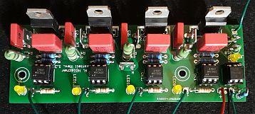
I designed a common board for the power modules of my dimmer and switch packs. One board carries four channels and one zero-crossing detection for dimming (not needed in switch packs). Also there is a single sided layout for running reduced loads. If less channels are needed, the board can be cut to the required length. Different optotriacs are used in the power modules of dimmer and switch packs!
Layout (112mm x 40mm; 300dpi)
Placement
thermal protection
In the course of increasing the power handling capabilities of the power modules, a thermal protection was necessary to prevent damage by shutting down the outputs. For this purpose, an NTC and the trimmer potentiometer R1 form a voltage divider, which triggers the shutdown if its value falls below 1.25V. I chose the following values for the voltage divider:
| R1 NTC |
10k (PT10-S) 6,8k @20°C |
For calibration, the NTC should first be heated to the desired threshold temperature (45°C - 75°C). Then R1 is first set to the right end stop (fully turned right) and then slowly turned back until the red LED lights up and the dimmer switches off.
Stand Alone Mode in DMX firmware
Switching on DIP10 activates the stand-alone mode if using the DMX firmware. The following settings are possible via the other DIPs:
| DIP1-3 | chaser |
| DIP5-8 | speed |
| DIP9 | flash |
RDM Firmware
RDM operation is activated via DIP10: In the ON position, DIP1 to DIP8 are used as part of the RDM device address. In the OFF position, DIP1 to DIP9 are used as the binary DMX start address as usual.
RDM parameters
The following settings can be accessed via RDM:
| Parameter | ID | Bytes | Function |
| DMX Start Address | 00F0 | 2 | DMX start address |
| Error Scene | 0302 | 8 | error scene on signal loss |
| Status Messages | 0030 | 9 | returns device status |
| Device Label | 0082 | 0..19 | name of device |
| Manufact. Label | 0081 | 5 | name of manufacturer (Henne) |
When setting the error scene, a "signal hold" functionality can be chosen by setting the channel to 128. A value of 0 turns off the corresponding output. A value of 255 turns it on.
Debugging
The ErrorLED should light up during start-up. A change in the relevant relevant DMX channels is acknowledged with a flashing of the green LED. An error is indicated by the ErrorLED flashing:
| Pattern | Error | Solution | |
|
|
single flashing | There is no signal present at the Transceiver. | Connect the Transceiver to the DMX bus. |
|
|
double flashing | The signal is not recognised as DMX. Not all required channels are received. |
Swap D+ and D- on the DMX connection. Transmit more channels or select a lower start address. |
|
|
on | Overtemperature | Allow to cool. If necessary, provide better heat sinks. Assemble thermal protection and use A-In. |